

When I started to learn how to write linux kernel drivers, the very first suggestion was to avoid writing them. I dont have the same recommendation for anybody – writing linux kernel drivers requires some additional knowledge, precision and patience, but its not that difficult. After all, its only standard C languguage with some specific kernel functions. What actually makes writing kernel drivers more difficult is the reduced ability to debug the code. IE, one should pay extra attention of what he is doing and think ahead of what might go wrong eventually. A good starting point is definitely to use the “printk” function along with DMESG command, but one may still find that insufficient under some circumstances. Furtunately, the kernel itself can be recompiled with additional debug capabilities,which are by default not included in the mainline kernel.
Before we start, I would like to also mention, that having a good information source by hand is priceless. My favorite book is the “Linux Device Drivers Development by John Madieu“. Its good to mention, that writing those drivers requires the knowledge of C language, optionally device tree syntax, at least basic linux terminal operation capability, knowledge of Vivado tool set and flow, RTL (VHDL / Verilog) and the actual device which you interfacing – this can be a simple AXI Timer , AXI DMA or really an arbitrary device with some kind of documentation. Its also worth to mention that an overall knowledge of the System is crucial (IE. Zynq 7000 / ZynqMP ) and their Technical Reference Manuals (TRM – these will be your new best friends). Also, do not try to write anything complicated until you have basic knowledge of how the kernel drivers work. Therefore, I highly suggest that a simple HelloWorld kernel module is your very first kernel module. Its also quite handy to have available test board with JTAG at least for RTL debugging (To be honest, I had some problems with my DMA driver and realized that thanks to my stupidity, I forgot to invert one of the signals – causing the drivers to fail the transfers of course … ).

There will be basically three parts:
- Hello World Example
- AXI Timer with interrupt handler and Device Tree modifications
- AXI DMA driver with very simple interrupt handlers
In the last part, we will also use DMA framework to manage the cache coherency issues, that cannot be solved from the user-space Linux program – IE. we are going to use AXI DMA connected to non-hardware cache coherency port of the ZYNQ 7000 – S_AXI_HP0.
HelloWorld
In order to build and run the helloworld module, the following conditions must be met: You have downloaded, compiled and deployed a known Linux kernel (Preferably from Xilinx GIT). In other words, you are not using petalinux, to create the image.ub for yourself – you have scripted and or build the entire bootable Linux image yourself. If not, you may be interested in this post. The Image.ub should include the DeviceTreeBlob, Linux Kernel and a RootFileSystem. Theoretically, the boot.bin containing the platform initialization could be build by the petalinux flow, although I do not recommend mixing any flows and or tools. If you don’t have a kernel, go ahead and download the latest Xilinx’s! I will be using Vivado 2019.1 along with linux-xlnx version 2019.1. My own compile environment is based on VirtualBox with 64-bit Ubuntu 18.04.5LTS. I have extracted the linux-xlnx package to “/Xilinx/linux-xlnx-xilinx-v2019.1/“.The first thing to do is to create a directory elsewhere, where we create a makefile for the module.
Makefile:
# Simple Makefile for creating custom kernel modules
# The Tool's location maybe found by "which arm-linux-gnueabihf-gcc"
# In order to Use petalinux: #1 IMAGE_INSTALL_append = "kernel-devsrc"
#                            #2 KERNEL_DIR:= ... Peta_Proj/build/tmp/work-shared/plnx-zynq7/kernel-source/

ARCH_Z7:=arm                                   # Architecture  "arm" for Zynq7000 / "arm64" for ZynqMP
CROSS_COMPILE_Z7:=arm-linux-gnueabihf-         # Crosscompilation ToolChain Version and selection
KERNEL_DIR:=/Xilinx/linux-xlnx-xilinx-v2019.1/ # Kernel Directory
MODULE_DIR  := $(shell pwd)                    # Module to be build's Directory

# Files to Include for Compilation
obj-m += helloworld.o  # Helloword    (Sample #1 - beechwood-hello-driver)
obj-m += request_irq.o # Request IRQ  (Sample #2 - beechwood-irq-driver)
obj-m += dma_example.o # Direct DMA   (Sample #3 - beechwood-dma-driver)


all:
	${MAKE} CROSS_COMPILE=${CROSS_COMPILE_Z7} ARCH=${ARCH_Z7} -C ${KERNEL_DIR} M=${MODULE_DIR} modules

clean:
	${MAKE} -C ${KERNEL_DIR} M=${MODULE_DIR} clean
Few more comments on this:
- ARCH = “arm” is the target for Zynq7000, for ZynqMP, use “arm64“.
- CROSS_COMPILE = “arm-linux-gnueabihf-” is the target for Zynq7000, for ZynqMP, use “aarch64-linux-gnu-“
- Each of the files to be compiled (*.o) needs to have a corresponding (*.c) file in the same directory.
HelloWorld:
#include <linux/init.h>
#include <linux/module.h>
#include <linux/kernel.h>
#include <linux/kern_levels.h>

MODULE_LICENSE("GPL v2");
MODULE_DESCRIPTION("Hello World Kernel Module");
MODULE_VERSION("1.0");

/*****************************
 *@brief Module Initialization
 *****************************/
static int __init hello_init(void){
   printk(KERN_INFO "Hello World!\n");
   return 0;
}

/***************************************************
 * @brief Returns from Kernel Module (Module Unload)
 ***************************************************/
static void __exit hello_exit(void){
   printk(KERN_INFO "Goodbye World!\n");
}

module_init(hello_init);
module_exit(hello_exit);
Few more comments on the HelloWorld Example:
After compilation, copy the helloworld.ko to your board/device and load it into the kernel via “insmod helloworld.ko“. You can review that the insert was successful by issuing “lsmod” command, which list all the kernel modules. Make sure to check also the output of the “dmesg” command, which should show an entry from the module “Hello World!“. After you have verified this, fell free to unload the module by “rmmod“. After removal, additional entry with “Goodbye World!” should be presented in the kernel log. No additional modifications to the FPGA / Device Tree were necessary in this example. Congratulations on your first kernel module!
AXI Timer with Interrupt Handler
In order to see how to implement an interrupt handler, we are going to use the mentioned AXI Timer IP core from Xilinx. The simplest option to use it is to instantiate the component in the IP Integrator (Block Diagram) containing already the PS-part of the processor (Either Zynq or ZynqMP processing system). We do need to access the AXI4-Lite interface of the IP as well as to route the interrupt line into the PS. The IRQ_F2P port needs to be enabled in the Processing System IP configuration to allow the PL to interrupt the PS. The IP Integrator’s address map needs to assign the AXI4-Lite address range for the timer either through GP_0 or GP_1 (For Zynq7000). The Choice is irrelevant as is the address. The address range must comply with the IP requirements (Usually, it is sufficient to dedicate 64 KB). The minimum working scheme is shown below (pdf here):
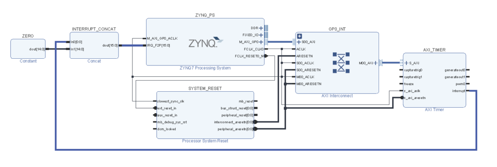
It is important to outline the concat block, which by default uses “auto” width for all ports. I HIGHLY recommend to not do this and specify instead manually the width of each port of the concat IP. The reason is, that if you connect your interrupt so that there will be some unused ports (IE. if your interrupt uses index 3, but index 2 is unused and configured to auto), then you are likely going to have a headache if you will modify the device tree by yourself and not by the tool. Because the tool knows that index 2 is unused and connects your interrupt to port 2 instead of port 3. Therefore manually specifying in DeviceTree to use port 3 will never work. Before we dwell into interrupt handler and DeviceTree, lets see how interrupts are defined there:
- DT-Node: “interrupts = <0 31 4>;” <X Y Z>
- X: Defines the interrupt to be either SPI or Non SPI. Note that SPI = Shared Peripheral Interrupt.
- Y: Interrupt Line Identification
- Z: Interrupt Sensitivity
Interrupt definition (X):
- 0 – Non-SPI Interrupt
- 1 – SPI Interrupt
Interrupt sensitivity (Z):
- 1 (rising edge) – Interrupt will be triggered only during transition from low to high.
- 4 (Level sensitive) – Interrupt will be continuously triggered as long as the interrupt remains high.
Interrupt Line (Y):
This is the most important number, double check it always. Lookup the corresponding TRM and find the Interrupt mappings into the GIC (Generic Interrupt Controller). You will find that: IRQPF2P[7:0] maps to [68:61] and IRQPF2P[15:8] maps to [91:84] (For Zynq7000). These “are” the numbers you are looking for. Well only in case if you specify the interrupts as SPI [1]. The truth is however that they are not shared, so that you have to specify 0 for them. As a result, the correct interrupt identification is “-32”. IE: IRQF2P[7:0] maps NOT to [68:61], but [36:29], 29 being the pl index 0. The Vivado tool and flow handles this for you, but in case you want to write it for yourself, you have to take extra care of that.
Before moving onto the DT, one last important thing: The Interrupt handler we are going to write later on MUST clear the interrupt flag (IE. The driver code within the interrupt service routine “ISR”). Lets see how the overall device tree entry looks like for the AXI Timer:
// -------------------------------------------------------------------------------------
// ------ PL AXI Timer AT Byte Addr 8002000 VIA GP1 & AXI4L Interconnect (Modified) ----
AXI_Timer: AXI_Timer_0@80020000 {
  clock-frequency = <100000000>;             // Clock Frequency
  clock-names = "s_axi_aclk";                // Clock Name
  clocks = <&clkc 16>;                       // Clock Taken from Zynq-7000.dtsi
  compatible = "xlnx,beechwood-irq-driver";  // Compatible Driver
  interrupt-names = "interrupt";             // Interrupt
  interrupt-parent = <&intc>;                // Generic Interrupt Controller
  interrupts = <0 59 4>;                     // Interrupt from PL to GIC (IRQ ID 91)
  reg = <0x80020000 0x10000>;                // Access on Address 0x80020000 (GP1) with 64KB Range
  xlnx,count-width = <0x20>;                 // Configured as 32 bit counter
};
Whats is most important: Again, the Interrupt identification and the “compatible” node, which says,which driver is compatible with the device. I did manually modified the default value (compatible = “xlnx,axi-timer-2.0″, “xlnx,xps-timer-1.00.a“;) to “xlnx,beechwood-irq-driver” so that the xilinx’s driver for their core is not used (The kernel will not know what driver to use for the DT node until we load our module). Also note the “reg” property, which defines at which address is the AXI4-L interface located. For this example, I have chosen 0x80020000, which is GP1 port of the Zynq PS (Yes, unlike in the previous picture) and has a dedicated range of 64KB (0x10000). Do not however try to load the device driver in case the memory address is not accessible (until the FPGA is programmed with the AXI Timer bitstream) – the system will freeze (More specifically the transactions to/from FPGA will hang forever). Other node properties are not extra important for us. You could remove the clocking section completely, as we not going to disable/enable/change the clock frequencies upon loading/removal of the kernel driver.
I have tried to make the code as self-explanatory, as possible, but anyway, the most important things. The module uses the platform drivers. Among the code, most important part is the table, which defines the compatibility options. Upon loading the driver, the kernel goes through the device tree and tries to find a compatible node, which in our case is the “beechwood-irq-driver“. The module must have a “probe” and “remove” functions associated. In the probe function, we register the interrupt handler by looking at the corresponding device tree node (irq_of_parse_and_map and request_irq functions). After registering the interrupt handler routine, we configure the AXI Timer to generate interrupts. In this example, I have chosen the interrupt period to be 0.25sec based on the frequency the timer is running on. This in my case is the FCLK_CLK0 PL fabric clock, which needs to have a frequency of 100MHz. Here comes the part that you should know how the FSBL has configured your platform in order to have this period. In case the period differs, then the FCLK0 clock is different than 100 MHz. The code that setups the period is based on PG079. A small hint here: The Xilinx’s timer generates an interrupt on the overflow of the 32b counter. Therefore you have to properly adjust the load value so that the overflow will occur in the required time (0.25s).
- Please find the underlying code HERE.
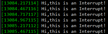
Upon successful module compilation, FPGA programming with a new bitstream, modification of the DeviceTree and insertion of the module, you should see a kernel log via dmesg similar to the following output (Note that the timestamp differences should be 0.25sec). Important note: Make sure the interrupt gets cleared in the handler! If not, then interrupts will be generated continuously (for level sensitive interrupt definition) so that the system will freeze! Also don’t forget to unregister the interrupt handler in the “remove” function.
DMA with Interrupts and Cache Coherency
I am going to utilize a standard AXI DMA (PG021) for this example and transfer some pseudo-random data on 100MHz clock from FCLK_CLK0. The DMA needs to use both S2MM and MM2S channels in direct register mode for simplicity (No Scatter-Gather nor Micro DMA mode). Furthermore, we assume that the S_AXI_HP0 port has a pre-configured width of 32b by the FSBL (Zynq has options to support 32b/64b. ZynqMP also supports 128b width). If we would use the hardware cache coherency ports (S_AXI_ACP for Zynq7000 and or S_AXI_HPC[0:1] for ZynqMP), we wouldn’t also need to worry about coherency and just write some basic user-space driver for the DMA, but because the intention is to not make things so simple, we will use the S_AXI_HP0 port of the Zynq PS. Lets start with the IP Integrator (pdf here):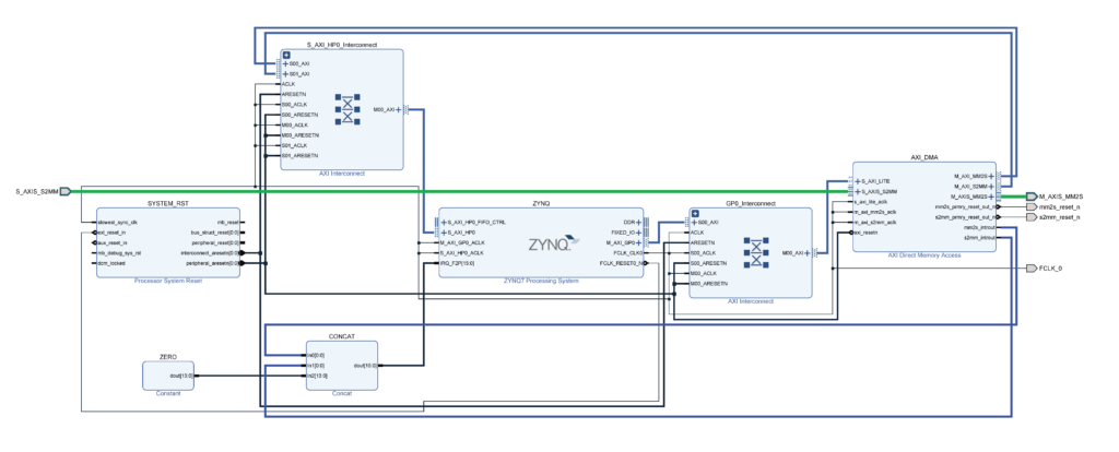
There is one AXI4 interconnect for the DMA’s AXI4-Lite interface connected to GP0 and another AXI4 interconnect before the S_AXI_HP0 port (Make sure your platform was initialized with the correct bitwidth – this would otherwise cause problems). All the clocks are synchronous in the design and the S2MM (Stream to Memory) and MM2S (Memory to Stream) interrupts are routed to the IRQ_F2P ports with indexes 0 and 1. What is not shown however in this diagram is how the S2MM and MM2S streams interact. This is external to the diagram and basically there is an additional Xilinx FIFO and a simple RTL code, which increments each incoming 32b word by 1:
----------------------------------------------------------
------- Testing Cache Coherency inside Linux Kernel ------
process(PL1_Clk)
begin
if rising_edge(PL1_Clk) then
HP_MM2S_Data_Vld_Reg    <= HP_MM2S_tvalid;
HP_MM2S_Data_Tlast_Reg  <= HP_MM2S_tlast;
HP_MM2S_Data_Reg        <= std_logic_vector(unsigned(HP_MM2S_tdata) + 1);
end if;
end process;
CacheFIFO:HP_DMA_FIFO
port map(
wr_rst_busy    => open,
rd_rst_busy    => open,
s_aclk         => PL1_Clk,
s_aresetn      => HP_MM2S_RSTN,
s_axis_tready  => open,
s_axis_tvalid  => HP_MM2S_Data_Vld_Reg,
s_axis_tdata   => HP_MM2S_Data_Reg,
s_axis_tlast   => HP_MM2S_Data_Tlast_Reg,
m_axis_tvalid  => HP_S2MM_tvalid,
m_axis_tready  => HP_S2MM_tready,
m_axis_tdata   => HP_S2MM_tdata,
m_axis_tlast   => HP_S2MM_tlast,
axis_prog_full => CacheCo_FIFO_FULL
);
HP_MM2S_tready <= not CacheCo_FIFO_FULL;
HP_S2MM_tkeep  <= (others => '1');
As you can see, the FIFO is there only because I didn’t wanted to bother myself with proper handling of the tready signaling (No FIFO is actually needed), so that instead a threshold of 500 out of 512 samples is considered a criterion when tready get deasserted for the MM2S. Anyway, its worth to mention that when an AXI DMA MM2S channel is reset, the reset is propagated into the FIFO (mm2s_rst_n and s2mm_rst_n signals). This is a good practice to reset the FIFO before starting additional transfers. For some application, it might be necessary to use FIFOs for both channels. However 1 FIFO is sufficient here since we are crossconnecting those 2 channels. Now that we have the RTL ready, lets move onto the device tree:
// ----------------------------------------------------------------------
// ------ PL AXI DMA Connected to Zynq HP0 Port (Custom Modified) -------
HP_RW_DMA: HP_RW_DMA_0@80400000 {
clock-frequency = <100000000>;             // Clock Frequency
clock-names = "s_axi_aclk";                // Clock Name
clocks = <&clkc 16>;                       // Clock ID
compatible = "xlnx,beechwood-dma-driver";  // Compatible Driver
interrupt-names = "mm2s_int","s2mm_int";   // Interrupt names
interrupt-parent = <&intc>;                // Interrupt Parent
interrupts = <0 31 4>,<0 32 4>;            // Interrupt IDs | Level Sensitive
reg = <0x80400000 0x10000>;                // AXI4L Base Address + Address Range
xlnx,addrwidth = <0x20>;                   // 32b Address Width
};
The reg property is as always based on the IP integrator’s address editor and this time represents the GP_1 port of the Zynq PS. Also the interrupt numbers are not identical to the picture provided. Correct would be to use <0 29 4>,<0 30 4>. The Reg property is useful in case we are going to parse the address from a device tree. In that case platform_get_resource and devm_ioremap_resource functions could be used. Since we however know the exact addresses (Well in fact also the interrupt numbers), the reg property is not of extra use for us and we can just use request_mem_region and ioremap_nocache. In fact writing an entire driver without the devicetree modification is an option, but its somewhat convenient to make the kernel module parse the parameters and modify any settings in the DT thereafter. Whats important is again the compatible property, which is set to “xlnx,beechwood-dma-driver“. This can be really an arbitrary string as long as the node matches the compatible property value in the module table.
I have also used an LCG generator in order to generate some pseudo random data and verify that there are no issues with the coherency and transfers (This is a PRN sequence generator, once data are generated with a seed, we can regenerate them again using the same seed – this is used in the code with the following command: Seed = Seed_Orig;). Quite obviously, we also need 2 buffers for RD and WR operations (Well theoretically a single buffer could as well be used for this purpose). The reset sequence of the DMA channels doesn’t matter, but I do recommend to start the channels in the following order: (S2MM and then MM2S). This way, you can be sure, that when data are coming from MM2S, the S2MM should be ready to accept them, since it has been configured previously and waits for valid transactions. Also there are 2 separate Interrupt handlers for the channels. Since the correct usage of Interrupts wasnt the goal of this exercise, they just mirror the “Polling” mechanism (which is by default omitted using IFDEF macros) and the only thing they does is that they clear the interrupt flags of the AXI DMA. The most important thing is however the following piece of code:
- dma_alloc_coherent
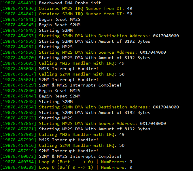
This function actually uses the DMA framework and guarantees that any CPU accesses to the allocated region are considered as “cache miss” – therefore accessing directly the memory region. On the other hand, this also implies that accesses to this memory are costly. It is however necessary for DMA operations to allocate the memory this way. The correct usage of AXI DMA is all based on the PG021 document. Additional information on controlling the DMA may be found here: Lauri’sBlog. Additional note on the configuration: CHAN_CR_IOC_IrqEn is the required flag in order for the DMA to trigger the interrupt. CHAN_CR_Err_IrqEn is optional. After FPGA bitstream update, device tree changes, module compilation and insertion, you should see a similar output in the kernel log as depicted below.
- Please find the underlying source code HERE.
Overall, I would say that writing Linux kernel drivers is not that hard, once you know the basics and limitations. The biggest problem is I believe finding a good source of information mostly due to the fact, the the majority of the embedded Linux developers and users just forward you to the kernel code documentation, which is in most cases useless if you are trying to understand a thing or two on a higher level. I really don’t understand this behavior. What is actually sad is that the internet is full of “half-usefull” answers and posts such as I described. That was primarily the reason why I have decided to publish this post.